
Basic Parameters
Diffuse Color
“Diffuse Color” is the diffuse color of the object. This value can be a flat color or a texture map.
Amount
“Amount” is the brightness of diffuse color. This value is multiplied with color, therefore by default 1, the final color equals the diffuse color. If weight is 0.5, the final color is 50% of its brightness.
Opacity Map
“Opacity Map” is the visibility of the object. This is mostly used as a silhouette technique for leaves, branches, and people. Reducing opacity is not the same as increasing “Refraction Amount” since in the first case you make the object “disappear” while in the second you would still see refractions and reflections. In this simulation
Roughness Amount
“Roughness Amount” is how rough a material appears. Hard surfaces like metals are usually rendered with the default value of 0, causing the object to look brighter at front angles. Rough materials like skin, rubber, and cloth tend to look more flat because they scatter light diffusely from every angle. Notice in the simulation how by increasing roughness the objects receive a more flat look. Remember if you increase roughness also to decrease “Reflection Glossiness”, rubber for example has not only rough diffuse color but also rough reflections, leaving reflections sharp would make it look not convincing.
Self-Illumination
“Self-Illumination” is the equivalent of a Maya shader’s “Ambient Color” or “Incandescence”. It’s used to self-illuminate an object like a TV monitor or light bulb. This value can also be higher than 1. Note however that this attribute is not meant to be used as a light source to illuminate a scene since it doesn’t give control over lighting quality. Instead, go to Create> V-Ray > Mesh lights > Turn selection into lights.
OFF
Compensate Exposure
“Compensate Exposure” lets you choose whether or not camera exposure adjustments affect “Self-Illumination”. If for example you increase the camera’s shutter speed you allow less light to enter the lens, this means light sources, primary illumination, GI, caustics and of course also self-illuminating objects become darker. In the simulation you can see that by leaving this attribute by default Off, the entire scene, including the light bulb, becomes darker. On the other hand, if turned On, camera exposure doesn’t alter the appearance of the light bulb. A rule of thumb is, if you’re happy with the look of the self-illuminating object, activate this attribute so you can freely adjust the scene’s exposure without affecting “Self-Illumination”.
Reflection
Brdf Type
“Brdf Type” determines the way a material reflects. “Phong” renders the fastest and is the only one where “Anisotropy” parameters are not available. This type is mostly used for plastic. “Blinn” is the second fastest at rendering and is used for chrome materials while “Ward” for brushed metals and steel. Notice how “Phong” has much sharper and harder reflections than the others.
Reflection Color
“Reflection Color” is the color of reflections. Usually it’s white for materials like plastic or covered in finish like car paint. In more diffuse materials reflections gain some coloring. Skin for example reflects a subtle bluish color, rust a brownish color; generally all reflections are slightly affected by the overall diffuse color and simulating it in the render adds realism.
Amount
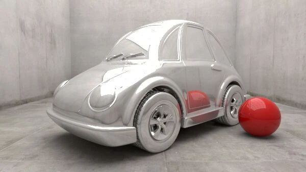
“Amount” is the object’s overall reflectivity. Since VRay shaders are energy conserving, reflection subtracts diffuse, this means that the more reflective the material become, the less diffuse color it emits. In this simulation you can see how with reflection amount 1 the car doesn’t emit any red color at all.
Reflection Exit Color
“Reflection Exit Color” is the color reflection rays render once they reach their “Max depth” value. Reflective materials cast reflection rays into the scene to determine which color to render, if they hit another reflective surface they bounce off again to determine the next color. The number of times they are allowed to bounce is “Max depth”, which by default is set to 5; in this simulation it’s set to 2 to show areas where they reach this limit and return the “Reflection Exit Color” instead of further bouncing within the scene.
ON
Lock highlight and reflection glossiness
“Lock highlight and reflection glossiness” is by default On and uses the “Reflection Glossiness” value for “Highlight Gossiness”. In this simulation you can see how by turning this attribute Off I am able to blur only the roof highlights while leaving reflections sharp.
Highlight Glossiness
“Highlight Glossiness” controls how blurry highlights appear. This attribute equals “Reflection Glossiness” as long as “Lock highlight and reflection glossiness” is activated. Notice how the scene’s reflections remain unchanged while only the rooftop highlights are affected.
Reflection Glossiness
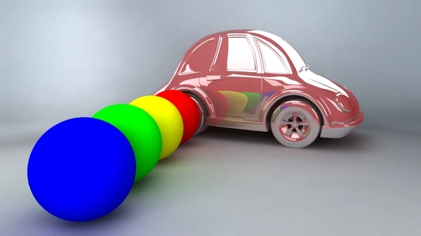
“Reflection Glossiness” is the blurriness of reflections. By default 1 reflections are glossy (sharp) like a mirror. The rougher a material is and the less glossy (matte) its reflections are, resulting in blurred reflections. Notice in this simulation how by increasing blurriness noise starts to appear, to solve this increase reflection subdivisions.
Reflection subdivs
“Reflection subdivisions” are the number of samples used to calculate reflections. The blurrier reflections are, the more subdivisions they require to render smoothly and consequently increase render time.
ON
Use Fresnel
“Use Fresnel” calculates reflections based on the Fresnel equation. This states that materials reflect more when viewed at low angles than from the front. In this simulation you can see that by turning this attribute Off the car is equally reflective at all angles and therefore appearing fake. “Use Fresnel” is by default enabled because it is true for all real world materials, plastic and shiny metals however need more frontal reflections and this is achieved by increasing the “Refraction IOR” to values between 2 and 20. Only for extreme cases like mirrors “Use Fresnel” should be turned Off.
ON
Lock Fresnel IOR To Refraction IOR
“Lock Fresnel IOR To Refraction IOR” is by default On and uses the “Refraction IOR” for the reflection “Fresnel IOR”. The reason these two values are linked is because in the physical world the degree of reflected light is proportional to the degree of refracted light. In this simulation, with this attribute turned On, the statue is rendered with both reflective and refractive index of 1.33, which corresponds to water. When turning this attribute Off, I increased the reflection IOR to 3 while leaving the “Refraction IOR” unchanged, notice in fact how the red poles we see through the statue (refractions) don’t change, but only how the material reflects. Be aware that turning this attribute Off does not produce physically correct results. In this example, by increasing the reflection IOR means that the material becomes harder, like metal, resulting in stronger front reflections, this should inevitably also cause refractions to become more distorted, and not left unchanged.
Fresnel IOR
“Fresnel IOR” controls how much light is deviated when bouncing off a reflective material. A value of 1 causes no change in direction, meaning that it has the same density as air. The harder the material, like chrome and metals, the more they reflect at angles facing the camera and therefore higher IOR values are required (between 10 and 20). For softer materials like rubber, where reflections are seen only at low angles, lower values are required. The question you should ask yourself while adjusting this value is: “does the material need more front reflections?” If the answer is yes, increase the value. A value of 0 stands for perfect mirror reflectivity.
ON
Trace Reflections
“Trace Reflections” is by default On and allows VRay to calculate reflections for the material.
Max depth
“Max depth” is the number of times reflection rays bounce to determine the reflection color. Once they have reached this limit they stop bouncing and render the “Reflection Exit Color”.
OFF
Reflect On Back Side
“Reflect On Back Side” is by default Off and prevents backsides of polygons to unnecessarily render reflections and therefore saving render time. The “Back Side” of a surface is the opposite side where Normals point. It often happens that an object seems not to render reflections at all no matter how high reflectivity is set to, the cause can usually be that the object has its Normals pointing inwardly and therefore its visible surface, being considered its “back side”, doesn’t render reflections. To solve this problem reverse its Normals or turn On this attribute. In this simulation the bottle has a single surface and by turning On this attribute we’re able to render reflections on both front and back sides.
OFF
Dim distance On
“Dim distance On” is by default Off and allows reflection rays to travel infinitely within a scene to calculate their reflection color. By activating this attribute you can set a distance at which these rays stop travelling and instead render the shaded points as non-reflective. This technique can be used to eliminate unwanted reflections coming from distant objects.
Dim distance
“Dim distance” is the distance at which reflection rays stop travelling.
Dim fall off
“Dim fall off” decays reflection rays resulting in a blurred transition between reflections and non-reflections. A value of 1 renders the reflection at distance 0 as opaque and gradually fades off till the “Dim distance” value. A “Dim fall off” of 0.5 renders opaque reflections from distance 0 till the half of “Dim distance” and then starts to fade.
Anisotropy
Anisotropy
“Anisotropy” stretches reflections to simulate parallel running micro fibers materials like CDs and brushed metals. When a surface is flat or homogeneously bumpy (isotropic), its reflections don’t change depending on the object’s rotation or direction, but when looking at a fiber carved material (anisotropic), they do. In such a situation, specular highlights tend to be elongated and run perpendicular to the direction of the grooves. The default value of 0 stands for a flat surface without anisotropy, decreasing the value stretches reflections horizontally and increasing the value stretches them vertically. Important: anisotropy does not work with the Blinn “Brdf Type” or if “Reflection Glossiness” is set to 1.
OFF
Anisotropy UV cords
“Anisotropy UV cords” allows you to map a texture file to change the UV coordinates used to calculate anisotropy.
Anisotropy Rotation
“Anisotropy Rotation” is the orientation of the microfibers. 0 stands for 0 degrees and 1 for 360 degrees.
Subscribe
Get notified when a new tutorial is posted. No newsletter, no spam.